|
|
|
 |
Radios Bench Spec's |  |
|
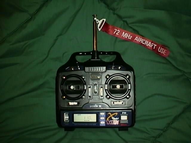
Radios Coroner: All Radio specs will be shown in later next month. This Site is still under Construction! AM vs. FM Radios AM and FM refer to the signal type. A radio wave of any frequency can have different signal types. AM (amplitude modulation) signals are easier to create so the equipment for them is more economical. FM (frequency modulation) signals have more range and are "cleaner" but can be more expensive. It works the same as your (full-size) car radio. When you listen to AM stations you sometimes hear static and interference. When you listen to FM stations, the static noise is greatly reduced. FM radios are less likely to have a problem with radio noise made from fuel burning engines and electrical power lines. AM radios are less expensive and work fine for most applications. If you live in an area that you suspect has lots of interference or plan to enter races with your car, FM could be your best choice. Radios, when used in a Sail Plane or Foam Wing, usually have a range of up to 1/4 mile. Switching crystals, modifying the antenna, running with weak batteries, etc., can all lead to diminished radio range. Check your radio's manual for more information. |
|
|
|
|
| Hitec RCD Radio: HITEC RCD FLASH 5 X for Gliders Flash 5 System X Five channel FM aircraft computer radio Then take a close look at the Flash 5 System X computer radio system. With high dollar features, such as five model memory, digital trims, "AutoSave"‚3 special flight modes for sport, electric or sailplane models as well as all of the most popular mixes, no other radio can touch the Flash 5 SX for quality and value. The Flash 5 SX is available in either a standard version with the deluxe HS-422 servos or as a micro system with the small HS-81 servos. Sloperdon owns one and I like how easy it is to set up any type of aircraft you have in a few minutes. Features 5 Channel Microprocessor Design 5 Model Memory Digital Trims Mode I Or Mode II Capable In-Flight Timer And Alarm Low Battery Warning End Point Adjustments For All Channels All Channel Servo Reversing Exponential Rates On Channels 1, 2 And 4 Data Reset To Defaults Trainer Jack Auto Engine Cut Switch 3 Pre-Set Mixes, Aileron - Rudder, Elevon, V-Tail Flaperon Capable 3 Flight Modes, Acrobat, Glider And Glider/acro Channel 5 Retract Switch Camber Adjustment Dual Rates On Channel 1 And 2 Proportional Flaps On Throttle Stick Electric Motor Controller 3 Position Switch Channel 1 And 5 Are Used For Two Ailerons Servos Allowing For The Use Of Very Creative Flaperon, Spoileron And Camber Or Reflex Mixes PROGRAMMING THE JR x-347 COMPUTER RADIO Computer Radios: If you like gadgets, you've got to have one of these. Their flexibility shortens construction time (simplifies control mechanisms) and the flight trimming that used to take all summer can now be done in a couple of days. I spent an extensive amount of time reviewing the Ace Micropro 8000, the Airtronics Vision 8SP, the JR x-347 and the Futuba Super 7. The Ace and the JR provide the most flexible programming. The template method of programming reduces the flexibility of the Airtronics Vision. However, there is a template available for every type of sailplane imaginable. The Futuba is restricted by limited programing and lack of dedicated mixing functions. I finally purchased the JR X-347 because it fit my small hands better and no one else in the local club owned one. Almost immediately after I purchased the radio, I began to hear rumors that the JR would not allow you to place the flaps on the throttle stick. However, I quickly discovered these rumors were not only false, but the JR radio allowed an incredible amount of programming freedom. The JR radio easily provides all of the programming necessary for a full function competition sailplane. Programming the JR is complicated by the fact that there may often be more than one way in which to accomplish the same result. Although more than one means may be available, it is important to select and use only one method to accomplish your objective. Otherwise, programming functions may be in conflict. The purpose of this article is to provide help in programming the JR for use in a six servo full function sailplane. It is important to realize that this is only one of many methods to accomplish the objectives below. If you disagree with my methods or you have found one that is better, please let me know what they are for use in a future article. This article also assumes you own a JR x-347, have the manual handy and are familiar with the six programming functions across the face of the radio. The page numbers referenced in the article are the page numbers found in the manual. The transmitter has two separate programming modes. These are the system setting mode and the function setting mode. Although the system setting mode comes at the end of the instruction manual, you must first set the system settings prior to the function settings. If you program the function settings first and then install the system settings second, it may result in wiping out your programming and returning to the system defaults. System Setting Mode: You enter the system setting mode by pressing and holding down the up and down buttons on the face of the transmitter and then turning the transmitter on. Once in the system setting mode, you need to name the aircraft (page 107), Select Aircraft Type, glider, (page 109), Inhibit V-Tail Mixing, (page 110) and Activate Dual Flap Mixing, (page 110). Then touch the up and down buttons simultaneously to exit the system settings. Function Setting Mode: After turning the radio on, touch the up and down buttons simultaneously to enter the function setting mode. You have now entered the section of the program that allows you to program and mix each servo in the airplane. First, place the servos in the wing so that arm-side of the servo faces the wing tip. If you plan to use the dedicated aileron differential mixing (which I strongly recommend), you need to reverse the aileron and flap servo connections. For some reason, the left and right aileron and left and right flap are labelled backwards in the instruction manual. Don't worry, it is easy to fix. Simply plug the left aileron into the right aileron socket on the receiver. Plug the left aileron into the right socket. Perform the same reversing for the flap servos. Now, check and make sure that all of the servos are working in the right direction relative to the stick movement. (At this stage of programming, you should have control over your aileron's, elevator and rudder.) Flaps will come later. To reverse a servo, push the up or down button until you enter the function mode identified on the screen as "Reverse SW" (page 87). Then press the CH key until you find the servo you need to reverse. Once there, touch the plus or minus keys to reverse the servo. If you have to reverse the ailerons (make sure you do both of them), go ahead and reverse the flap servos while you are here. Set End Point Adjustments: Next, enter the end point adjustments. Touch the up or down key until T.ADJ appears on the lower part of the screen (page 89). Touch the CH key to identify the servo whose end point you wish to adjust. Then, hold the appropriate stick all the way to the stop and touch the plus or minus key until the control surface goes in the proper direction and the desired distance. Each control surface has two separate end points. Left and right or up and down. Simply repeat the above, but push the stick in the opposite direction and then set the end point. The transmitter defaults are set at 100 percent. These can be adjusted from zero to 150 percent. I recommend setting more down elevator than up to help control pitch up when flaps are lowered. Leave flaps at 100 percent for now. Aileron Differential: There are two different ways to set aileron differential. One is to use the end point adjustments described above and the second is to use the differential aileron mixing function (page 92). I prefer to use the differential aileron mixing function. That way, if I want to modify the differential mixing, changing one setting not only changes both aileron servos, but makes the same differential adjustment to both flap servos if the flaps are mixed to the ailerons. Otherwise, you would have to change the end point adjustments on four separate servos. By reversing the left and right servo and left and right flap you can now take advantage of differential mixing. If you plug the ailerons and flaps in per the manual, you still have differential mixing; however, it is backwards. Enter differential mixing by pressing the up or down key until MIX DIFF appears on the screen. Initially set the differential to 100 percent by pressing and holding the plus or minus key. Moving the aileron stick will now force one aileron up, but the other one will not go down. Now hold the aileron stick all the way to one side. If you want more or less up aileron, return to the end pointed adjustment section above and make the appropriate adjustment. If the amount of up aileron is in the ballpark, hold the aileron stick all the way to one side and push and hold the plus or minus key until the opposing aileron comes down the desired amount. Differential mixing works for both ailerons. Push the stick the other way and you will see that the mixing effect is the same on both ailerons. If the ailerons go up different amounts, re-enter the end point adjustment described above and modify the end point adjustments until both ailerons go up the same amount. Trailing Edge Camber and Reflex: On the upper left hand side of the transmitter is a knob identified in the manual as the flap knob (page 101). However, because you are going to place the flaps on the throttle stick (explained in greater detail below), you can re-program this knob to adjust trailing edge camber. Press the up or down key until FLAPP TADJ appears on the left side of the screen. Press the plus or minus key until the right side of the screen reads approximately 10 percent. This knob now acts as a trim knob for the two-flap servos. On my current aircraft, this gives me approximately three percent up and three percent down at the trailing edge. To get the entire trailing edge to reflex or camber, press the plus or minus button until MIX FL-A appears on the left side of the screen (page 93). Set the mixing value to 100 percent. Now, reflex or camber of the entire trailing edge can be adjusted at any time by simply turning this knob. Rudder to Aileron Mixing: There are four programmable mixing functions allowing you to mix any stick movement to any other servo on the model. These are labeled MIX A through D. Mix - Ds primary setting is master two to slave four (aileron to rudder). Mix D differs from the others in that the mixing values for left and right are the same and no offset point can be set. Press the up or down key until MIX D appears on the screen (page 97). Press the CH button until MIX D CH appears on the screen. Press the plus key until 2 appears on the master channel setting and press the minus key until 4 appears on the slave channel setting (page 99). Press the CH key until MIX D SW appears on the screen. Press the plus or minus key until MX SW appears on the screen (page 99). This allows you to turn the aileron to rudder mix on and off with the long switch in the upper right and rear of the radio. Press the CH button until MIX D 2 4 appears on the screen. To the far right of the screen, there should be a zero with a percentage symbol. Standing behind the airplane, press the aileron stick all the way to the stop. Press the plus key until the rudder goes the appropriate distance. If the rudder goes in the wrong direction, re-set the mixing value to zero by pressing the clear key and then pressing the minus key until the rudder goes in the appropriate direction and the appropriate distance. Simply modify the percentage of the mixing value to increase or decrease the amount of rudder to aileron mixing. Operating the Flaps from the Throttle Stick: This section places the flaps and elevator compensation on the throttle stick. Although it appears from the instructions that there are other dedicated mixing functions for this, I strongly recommend using programming MIX B and C. The other dedicated flap mixing functions assume that flaps will be controlled by the knob on the upper left hand side of the radio. To control flaps from the throttle stick, you must use the programmable mix functions. Enter MIX B by pressing the up or down key. Press the CH key until MIX B CH 1-1 appears on the screen. Press the plus key to set the master channel to one. Press the minus key to set the slave channel to three. (This channel will be used to mix an elevator compensation.) To set the operational switch setting, press the CH key until MIX B SW appears on the screen. Press and hold the plus or minus keys until ON appears to the right. This sets the operational switch setting so that elevator compensation is on all of the time. Press the CH key until MIX B 1-3 OFFSET appears on the left side of the screen. I like to set my flap stick so that the stick is at the top for neutral flap and the stick is at the bottom for full 90 degree flaps. To accomplish this, push the throttle stick all the way to the top and press the clear key. This stores the offset position. The right hand side of the screen should read approximately 170. Finally, enter the mixing value. Press the CH key until MIX B 1 3 appears on the left side of the screen. The right side of the screen should read zero percent. Pull the throttle stick (now the flap stick) all the way to the bottom. Press and hold the plus or minus key until you achieve the proper amount of elevator deflection and in the proper direction. Next, we need to mix the throttle stick to the flaps. Press the up or down button until MIX C appears on the left side of the screen. Press the CH key until MIX C CH appears. Then press the plus key until one appears for the master channel and press the minus key until six appears for the slave channel. As you did before, set the operational switch setting to ON. Now this is where it gets interesting. Typically, even when mixing extensive elevator compensation, many models still balloon when the flaps are initially lowered. By setting a different offset for the flap than you have for the elevator, you can program the radio so that as you begin to bring down the flap stick, a slight amount of down elevator occurs before the flaps begin to move. To achieve this, press the CH key until MIX C 1 6 OFFSET appears on the left side of the screen. Move the flap stick all the way to the top, then bring it down three or four clicks and press the clear button to set the offset. The offset function should be approximately 136. By having different offsets, elevator compensation begins slightly ahead of the lowering of the flaps. This has completely eliminated any tendency of my current aircraft to balloon on approach. You may need to experiment with your own values. Finally, set the mixing value by pressing the CH key until MIX C 1 6 appears on the left side of the screen. Pull the flap stick all the way to the bottom and touch the plus or minus button until you achieve the desired amount of flap. If for some reason flap movement is insufficient, you may need to change the end point adjustment for flap and auxiliary two. If this is still not enough, you may need to vary the length of the servo arm or of the flap horn until you achieve full 90 degree flaps. To adjust the flap in the up position, use the sub trim adjustment (page 88). Dual Flap Trim: Pots 5 and 7 are the trim knobs on the right hand side of the transmitter. I strongly recommend inhibiting the action of both of these knobs. They are too easy to bump in the impound area and these adjustments can easily be made on the ground using electronic sub trim. Also, if you are flying Mode 2, you don't want to take your hand off the stick to adjust either of these knobs. Elevator to Flap Mix: My larger sailplanes are flying with either an SD7037 air foil or a combination of an SD7032 that tapers to an SD 7037 at the tip. I find that with both of these air foils, thermal capability is enhanced by mixing trailing edge camber with up elevator. This can easily be accomplished by using the dedicated elevator to flap mixing function (page 90). The long slender mixing stick immediately above the throttle stick should be moved to the upper position. This mixing function can be turned on and off in flight with this switch. This switch must be in the ON (upper) position for the mixing values to be set. Press the up or down key until MIX E-FL appears on the left-hand side of the screen. Pull up elevator all the way to the stop. Press the plus or minus key until you have achieved the proper amount of trailing edge camber with full up elevator. (This is usually around ten percent on my models.) Launch Flaps: In the upper left front corner of the transmitter is a switch labelled CROW. This switch is discussed in detail under the butterfly/crow mixing function in the manual (page 94). I like to place my pre-set launch flaps on this switch so that at the top of the launch and immediately prior to zoom, I simply flip a switch to return the flaps to the normal flight position. I do not use the flap stick for launch flaps. Press the up or down key until MIX SP appears on the left side of the screen. Press the CH key until MIX SPOI OFFSET appears. Hold the flap stick at the exact center and press the clear button. The offset should be as close to zero as possible. This may take several tries. Press the CH button again until MIX SP:F appears on the left side of the screen. If you flip the CROW switch back and forth, you will see that the switch position varies between zero and one on the display. Push the switch to the back (launch flap position). With the flap stick in the "up" position, press the plus or minus key until you have the proper amount of launch flap in the right direction. At the top of the launch curve and immediately prior to zoom, pull the switch forward which re-sets the flaps to normal flight mode. Crow: Adding crow is probably the most difficult function. There must be an easier way, but I have not found one yet. With the crow switch in the normal flight position, press the CH key until MIX SP:A appears on the left side of the screen. Pull the flap stick all the way to the bottom, press the plus or minus key until you have the desired amount of crow. (Both ailerons will go up.) Then, flip the crow switch to the launch flap position and enter the exact same mixing value. You should now be able to switch back and forth between crow position zero and one and the ailerons will not change. However, the aileron will appear to be stuck in the up position. You now have to enter the sub trim adjustments for aileron one and aileron two and change the sub trim until the ailerons are in their proper position when the flap stick is all the way up. Now, when you pull the flap stick down, the flaps will go down, the ailerons will go up and elevator will compensate. Flap Adjustments: The flaps in the up position can now be adjusted using sub trims (page 88 to adjust the flaps). To adjust the flaps in the down position, pull the flap stick all the way down and change the end point adjustments (page 89). If flaps still do not come down far enough, you may need to make further changes to the end point adjustments or increase the mixing percentages in program MIX C or change the length of the servo or flap arms. Dual Rate/Exponential Rate: Who needs dual rates when you have exponential mixing? Exponential mixing takes the twitchiness out of stick center. I use it in all functions, especially the elevator to smooth the flight of the aircraft. Although the flight of the aircraft is smoothed out, similar to what dual rates would do, you still have full throw on all of your control surfaces at full stick movement. This is something that I would fully encourage you to experiment with. The first time you program this radio, it is going to take you some time. However, the functions are very easy to get used to, especially if you consistently program all of your aircraft the same way. As stated in the beginning of this article, this is only one of many possible methods for programming this radio. JR is offering a upgrade, which I believe turns the three position switch immediately above the flap stick into a three position trailing edge camber switch. I believe there are some other functions involved, but I do not know what they are. Although the above may sound complicated, believe me, it is a lot simpler than trying to mix all of these various functions mechanically. The ease with which you can make adjustments in the field to any of the mixing parameters, makes the trimming and balancing of an aircraft simple. It also encourages you to experiment with different trim settings, because they are so easy to do. Instead of taking the whole summer of bending, twisting, lengthening and shortening cables, and servo control horns, all of the adjustments can be made with the radio. If you can afford one, the time saved and the ease with which an aircraft can be trimmed and balanced with the computer radio was well worth the money spent. If any of you have any different means of programming a six servo setup using a JR X-347, please let me know. Over time, I would like to assemble different ideas on programming this radio. Please give me a call at (206) 455-2345 PST or send me a copy of your data sheet to 1000 Plaza Center, 10900 Northeast Eighth, Bellevue, Washington 98004. This is a great radio. The radio performed all of the functions that I needed at a relatively inexpensive price. I hope you found the information useful. Good luck and good flying. |
|
|
|
|
| |
|
|
|
|
| |
|
|
|
|
| |
|
|
|
|
| |
|
|
|
|
| |
|
|
|
|
| |
|